

Sau bài này các bác có thể dán mấy cái hình như này lên 3 mặt phẳng của solid để làm gì thì làm tuy tếng anh nhưng khá dễ dịch các bạn cứ làm theo chỉ dẫn trong hình hoặc theo googletralate mà dịch
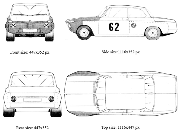
Yêu cầu cắt đúng kích thước, có phần mềm nào đó để edit ảnh thì càng tốt. Để đề phỏng mình kiếm sẵn cho các bạn cái cắt rồi đây.


Rồi bây giờ thì làm theo hướng dẫn
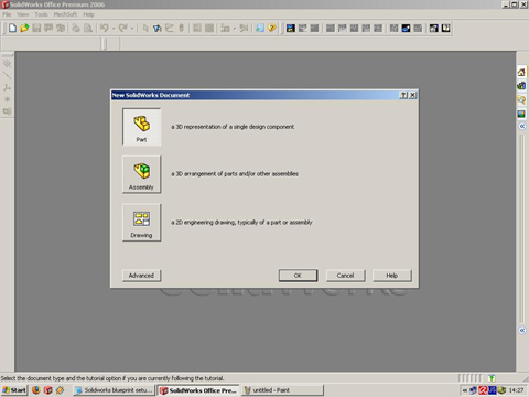
mở Solidworks và click menu File > New > Part chọn Ok
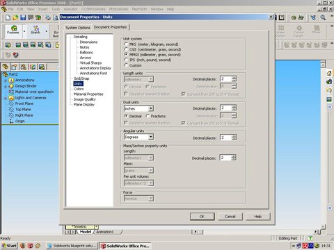
tiêp menu Tools > Options > click on the Document Properties tab and click on the UNITS, and make the settings like this:
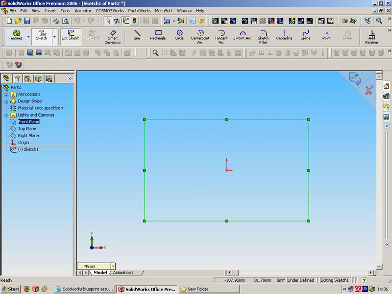
and click ok. than we must make the Plane views (Front, side, top, back). Click on the Front plane in Solidworks Feature manager, right click on the mouse and click INSERT SKETCH like that
then go to Menu TOOLS > Sketch Tools > Sketch Picture like this:

Now browse to the place or root folder of the separated cropped images for each one views (front, side, top, back), which you made with the picture editor program and choose FRONT

now we must to setup the symmetry line/point of the coordinate system, the dimension of Axis X and Y division into two like this

then click Exit sketch in the right upper angle of the window. For other Planes the funktions is same: Right Plane > right click on the mouse > Insert sketch > Tools > Sketch Tools > Sketch picture > and choose the right picture for a view like this setup of the units:

For a top plane the technique is the same: Top Plane > Insert sketch > Tools > Sketch Tools > Sketch Picture and choose the picture for a top view, in this way we must rotate the sketch 90 degrees. For property result here in this plane we must change the positions of the dimensions of X and Y axis like on the picture 1116 / 2 = 558mm with ' - ' to change the direction and rotation of 90 degrees, for a X axis we have 447 / 2 = 223.5mm, like on the picture:

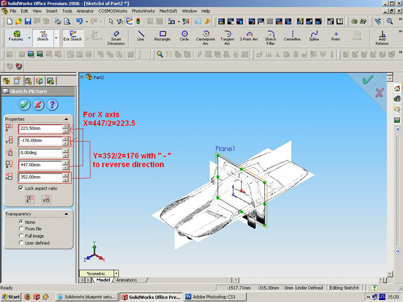
then click exit sketch in the right upper corner of the window, and finally we must insert sketch for a Back view like another planes: Here we`ll using a Front plane, select front plane and from MENU > Insert > Reference Geometry > Plane

For selections must be a Front plane the Dimension may be another not 80mm your choice, must be marked Reverse direction, and click OK. Now in the FEATURE MANAGER tree must have Plane1 right click on the Plane 1 > Insert Sketch > Menu Tools > Sketch Tools > Sketch picture > and choose the picture for the back view, then must setup the dimensions on X and Y axis:
click OK and Exit Sketch, so that is you can rotate or change views to see the final results, i hope than this Blueprint`s setup tutorial will help you,
nguồn vinamec.com
Yêu cầu cắt đúng kích thước, có phần mềm nào đó để edit ảnh thì càng tốt. Để đề phỏng mình kiếm sẵn cho các bạn cái cắt rồi đây.
mở Solidworks và click menu File > New > Part chọn Ok
tiêp menu Tools > Options > click on the Document Properties tab and click on the UNITS, and make the settings like this:
and click ok. than we must make the Plane views (Front, side, top, back). Click on the Front plane in Solidworks Feature manager, right click on the mouse and click INSERT SKETCH like that
then go to Menu TOOLS > Sketch Tools > Sketch Picture like this:
Now browse to the place or root folder of the separated cropped images for each one views (front, side, top, back), which you made with the picture editor program and choose FRONT
now we must to setup the symmetry line/point of the coordinate system, the dimension of Axis X and Y division into two like this
then click Exit sketch in the right upper angle of the window. For other Planes the funktions is same: Right Plane > right click on the mouse > Insert sketch > Tools > Sketch Tools > Sketch picture > and choose the right picture for a view like this setup of the units:
For a top plane the technique is the same: Top Plane > Insert sketch > Tools > Sketch Tools > Sketch Picture and choose the picture for a top view, in this way we must rotate the sketch 90 degrees. For property result here in this plane we must change the positions of the dimensions of X and Y axis like on the picture 1116 / 2 = 558mm with ' - ' to change the direction and rotation of 90 degrees, for a X axis we have 447 / 2 = 223.5mm, like on the picture:
then click exit sketch in the right upper corner of the window, and finally we must insert sketch for a Back view like another planes: Here we`ll using a Front plane, select front plane and from MENU > Insert > Reference Geometry > Plane
For selections must be a Front plane the Dimension may be another not 80mm your choice, must be marked Reverse direction, and click OK. Now in the FEATURE MANAGER tree must have Plane1 right click on the Plane 1 > Insert Sketch > Menu Tools > Sketch Tools > Sketch picture > and choose the picture for the back view, then must setup the dimensions on X and Y axis:
click OK and Exit Sketch, so that is you can rotate or change views to see the final results, i hope than this Blueprint`s setup tutorial will help you,
nguồn vinamec.com